Non-destructive testing provides valuable information and can reveal unanticipated or hidden deterioration.
Non-destructive testing (NDT) uses innovative methods to evaluate the condition and durability of reinforced concrete structures— quickly and accurately. There’s a variety of NDT technologies available, and our experts can help identify the right technology for a project. And we’ll work with you to assess the complex data collected from NDT equipment.
Curious to see how cutting-edge engineering techniques are transforming bridge rehabilitation?
Watch this video explore some of our non-destructive testing methods in action and discover how we're ensuring the longevity and safety of critical infrastructure - CLICK PLAY NOW!
Methods
Our experts will help you determine which methods are most effective and economical for your needs.
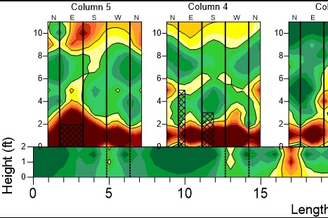
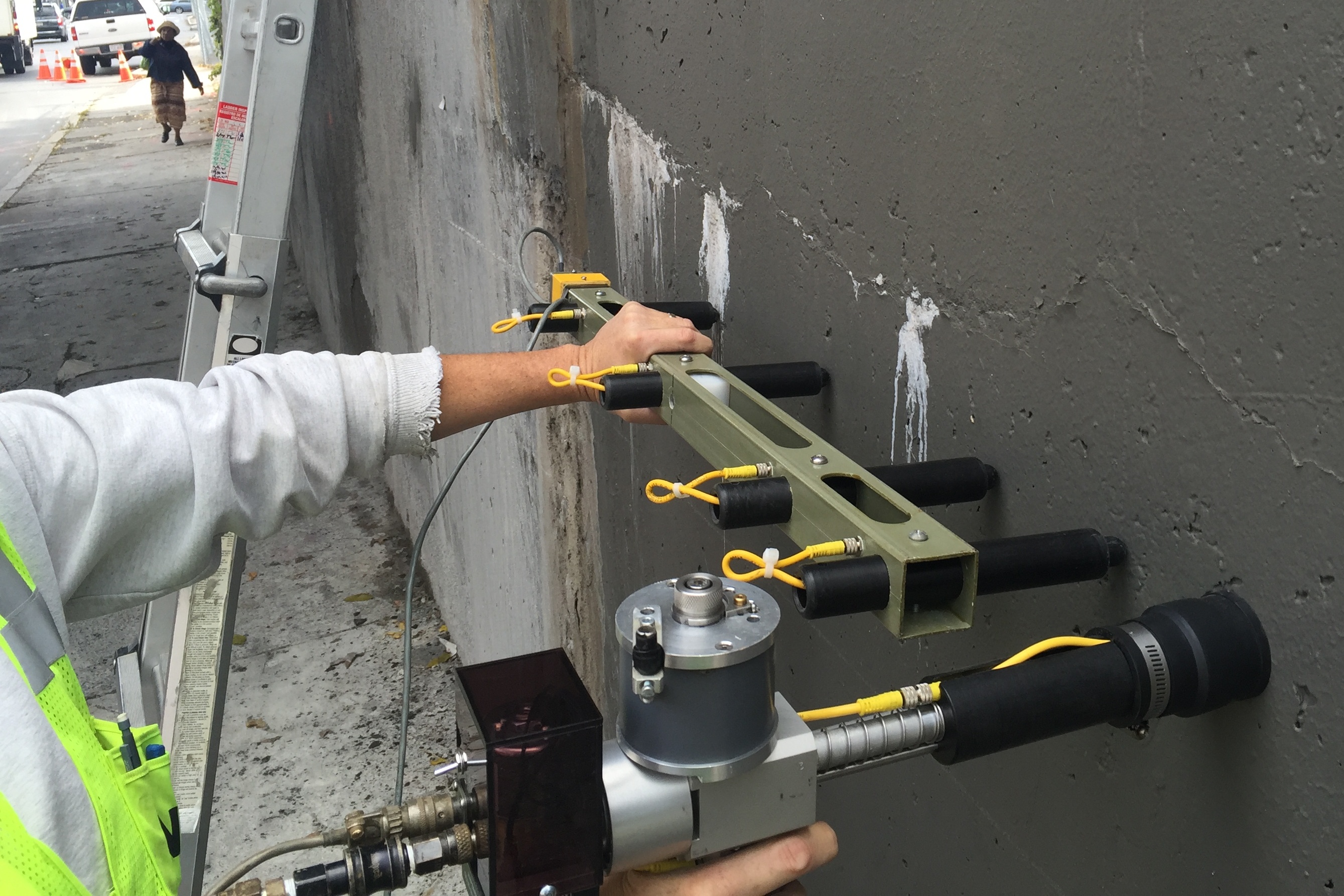
Acoustic Tomography
Our engineers can create 3-dimensional acoustic images of reinforced concrete elements to identify areas of potential defects or damage within the elements that cannot be observed through visual inspection. VCS places an acoustic transmitter and receiver on opposite sides of a concrete structure and collects the compressional wave velocity through the element. This procedure is repeated over a dense survey grid along the structure. This dense grid provides the wave velocity throughout the structure, which can be modeled 3-dimensionally to offer a detailed map of wave velocities throughout the structure. Areas, where the velocity is below average, indicate fractures, cracking, honeycombing, low-strength concrete, or voiding within the concrete. This methodology can also perform QA/QC for concrete repairs. By performing acoustic tomography on a cracked or honeycombed structure, the location of these defects can be accurately identified. Then, a contractor can repair these defects, and the acoustic tomography is repeated after the repairs are completed to ensure that the voids no longer create anomalies in the image. This ensures that the voids/honeycomb are entirely repaired.
Concrete Resistivity
The electrical resistivity of concrete is an essential factor in the corrosion process of embedded reinforcing steel.
If the concrete resistivity is low, it can provide a favorable environment for macrocell corrosion. In addition, the spatial variation of resistivity measurements is often related to risk with corrosion activity, making surface resistivity a reasonable surrogate for corrosion potential testing on epoxy-coated reinforced concrete decks.
Resistivity is also an essential factor in the design of cathodic protection systems.
Corrosion Potential Mapping
Our engineers collect corrosion potential measurements to determine the risk of corrosion of embedded reinforcing steel and submerged steel structure.
Our expert team measures the electrochemical potential difference between different points on a concrete structure. By interpreting this measurement, we generate a map of the corrosion probability. These measurements are essential when considering the effectiveness of global or targeted corrosion mitigation strategies.
Corrosion Rate Testing
We perform corrosion rate testing to determine the rate at which steel section loss is occurring. In corrosion rate testing, we use different polarization methods to determine the rate of corrosion. We apply an external current to the structure and monitor potential changes to calculate the corrosion rate. This information helps our team:
- Understand the level of corrosion in different parts of a structure
- Determine the appropriate cathodic protection system to prevent further corrosion
- Estimate the rate of deterioration of the structure
Ground Penetrating Radar
A ground penetrating radar (GPR) can accurately and efficiently identify the location and cover-depth of steel reinforcement in concrete structures. In addition, GPR can provide a qualitative assessment of the condition of reinforced concrete to identify deterioration. GPR is a rapid test method that can provide a cost-effective assessment of an existing structure or help an engineer understand the as-built condition. GPR can also determine the thickness and layering of pavements for roadways.
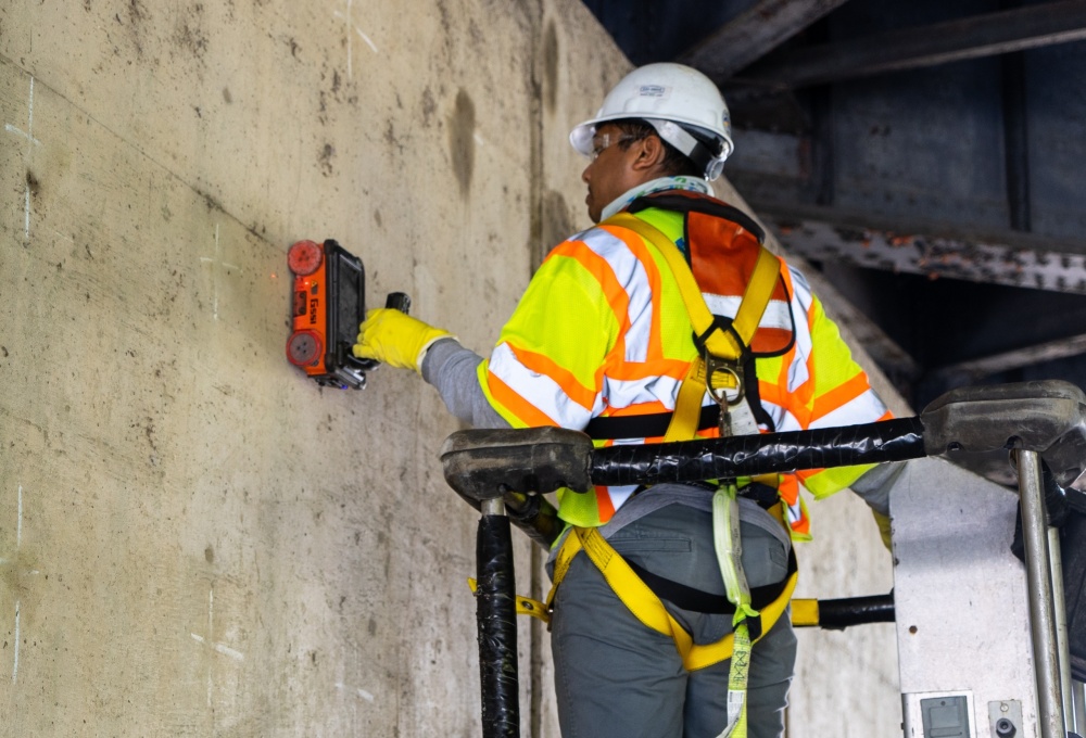
Impact Echo and Pulse Echo Velocity
Impact echo/pulse velocity (IE/PV) testing is a non-destructive method that determines concrete characteristics and identifies delamination, cracking, and voids by applying stress waves imparted into the concrete. Our custom, state-of-the-art IE/PV system is the only system in the industry that simultaneously collects the IE and PV data, saving us precious time when assessing structures. In addition, IE/PV can assess the in-situ concrete compressive strength and locate defects like honeycombing, cracking, and delamination.
Infrared Thermography
We use Infrared Thermography (IR) to identify delaminated concrete over a large area in a short period of time. As the sun heats a concrete surface, the temperature of delaminated locations increases faster than sound concrete. This temperature differential is observable with an IR camera. The IR image creates a visual record of delaminations useful for estimating repair quantities. Large near-surface delaminations are more easily identified as IR is comparable to a hammer-sounding survey.
Railroad Tie Testing
Concrete crossties are crucial for global rail networks, ensuring safe freight and passenger operations. Assessing each crosstie's condition is vital for rail transit safety. Traditional visual inspections, whether by personnel or high-speed imaging, only evaluate external conditions, overlooking internal deterioration that precedes surface damage as damage is already severe when observed. VCS addresses this with the Automated Concrete Tie Tester (ACTT) system, utilizing non-destructive pulse velocity (PV) evaluation. The ACTT provides real-time ratings (1-5) based on internal conditions, automating maintenance decisions for crossties with severe damage (4 and 5 ratings).
Ultrasonic Thickness
An ultrasonic thickness (UT) gauge can measure the thickness of steel elements. UT identifies a metal’s thickness by measuring the travel time of an ultrasonic signal through steel. We can use UT measurements to determine the remaining cross-section of corroding steel elements. To determine the corrosion rate, we use the age and original thickness of the structure. Then, we use UT measurements to measure the amount of section loss that has occurred and calculate the rate of section loss. In addition, VCS uses UT to measure the length of bolts and if there are any cracks or fractures along their length. VCS commonly performs UT on roadway signage bolts to confirm their condition, as these elements have been known to corrode, leading to signage failures that lead to the signs crashing down into the roadway.
Project Experience
We provide extensive experience across a range of structures and environmental conditions.
Where it Applies
Service offerings are relevant across these sectors.